The making of the MarioCube
I have volunteered to create a demo for a STEM event with the theme of bits. I wanted to create something that would interest these young minds, but as always I wanted as well to learn frm the project myself. While scouring the web for inspiration I found different projects involving Arduino and LEDs, and this is when the inspiration came:
create an animated led cube
How does it relate to the topic of bits you might ask? I will explore that in detail later.
Bill of Materials
For this project I used:
- 1x Arduino Uno
- 4x Individually addressable WS2812B 16x16 panels
- 1x 5V 3A wall power supply
- Lots of cables :D
WS28112B what is it?
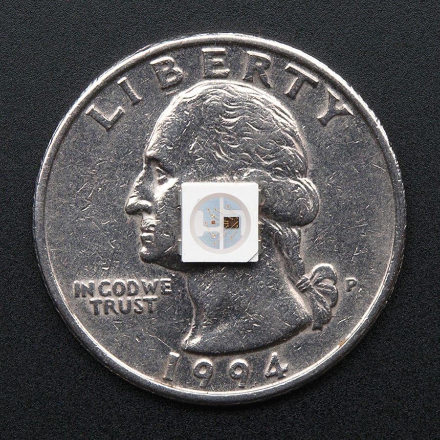
The WS2812B is an RGB LED that combines a control circuit and light source into a compact package. The integrated design simplifies wiring and installation while maintaining precise control over each LED’s color and brightness. The internal components include an intelligent digital port for data handling, a signal reshaping and amplification circuit for maintaining data integrity, and a precision oscillator for consistent performance. A built-in constant current regulator ensures uniform brightness and color accuracy, even with voltage fluctuations.
Each LED processes its data, reshapes the remaining signal, and passes it to the next in the chain, allowing for seamless cascading. The design supports unlimited chaining in theory, limited only by practical factors like power and data transmission speed.
Bit depth and colors
A single WS2812B LED receives 24-bit data packets (8 bits each for red, green, and blue) to control their color. This is generally referred as a 8 bits per pixel depth.
 The WS2812B bit packet for color representation
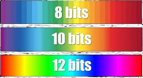
Bit depth quantifies the number of unique colors or shades an image or display can represent by specifying each color using binary digits (0’s and 1’s). It defines the precision of color representation but does not mean that all possible colors are used. For grayscale images, bit depth describes the number of shades available, while for color displays, it determines how many combinations of primary colors can be represented. Higher bit depths enable richer, more detailed color or shade gradations by providing more combinations of binary values.
Each pixel or LED in a display combines the intensities of three primary color channels: red, green, and blue. The bit depth per channel, or “bits per channel,” specifies the intensity levels for each color. “Bits per pixel” (bpp) refers to the total bit depth across all three channels, representing the total number of colors that can be displayed. For example, in an 8-bit per channel setup, each pixel can display
256 * 256 * 256 = 16’777’216 total colors.
 Comparison of different bit depths, with increasing bits per pixel
Layout of WS28112B panels
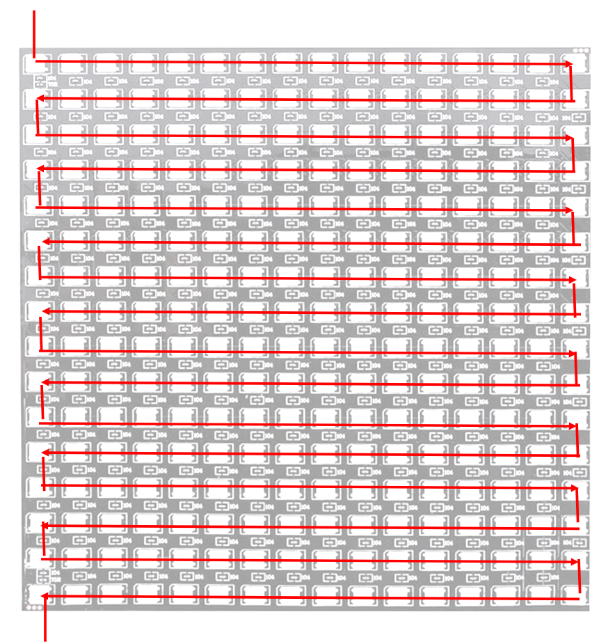
Each LED is linked to the next in a daisy-chain configuration, making it essential to understand the panel’s layout to properly address each LED. For example for the panels I got the layout is as follows
This layout is known as serpentine, and the rows alternate the direction depending on their index. In particular:
- for odd rows the direction is from left to right.
- for even rows the direction is from right to left.
Hardware: wire it up
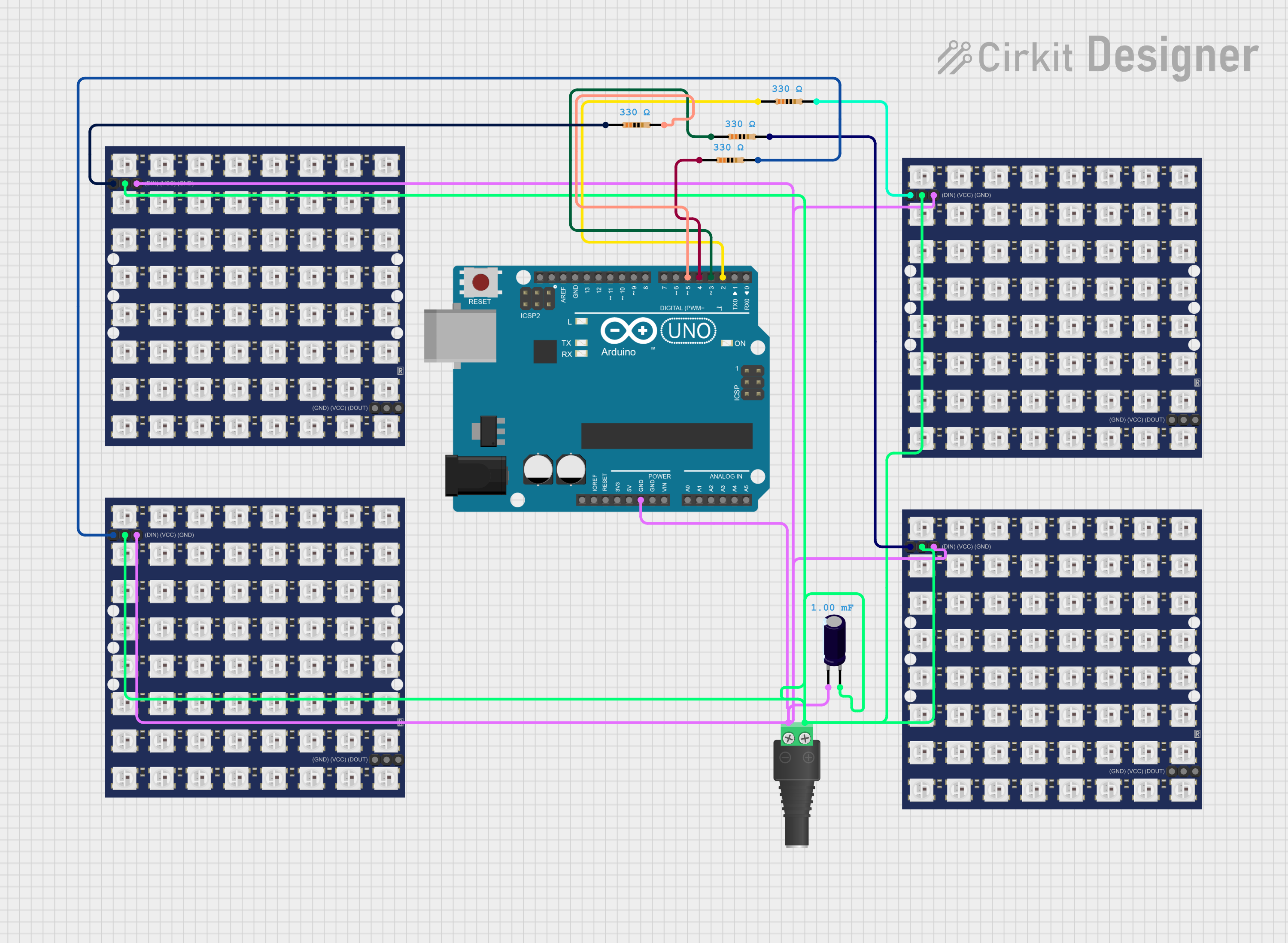
To make sure the 1024 LEDs would get enough energy I have opted to use a 5V 3A wall power supply, while the arduino is powered via the USB while connected to the PC. To protect the LEDs from power fluctuations I have also use a 1mF capacitor. Also to protect the data line of the four panels I have installed 4 330Ω. The full schematics is shown below.
You might notice that in the image 8x8 led panels are shown, this is simply a limitation of the tool I am using to draw the circuit. Also, I have decided to connect every panel to a controller and not to daisy-chain them, this is because of memory limitations on the Arduino Uno that make it impossible to allocate a single array of 1024 LEDs.
Software: code it up
The softtware layer is comprised of two different components: a Python component to process gifs and images and then the C++ code for the Arduino.
Python layer
For the Python layer I have written two different scripts:
1) A script to separate in different frames gifs that I have found on the web. 2) Once I identify the frame I need, I need to save its RGB values in the format
0XFFRRGGBB
where 0x indicates a hexadecimal number, FF is not used but is added as packing as Arduino does not natively support 24 bits number, and finally RR GG and BB represent respectively the values associated to the red, blue and green values respectively. An important note is that to be represented on the LED matrix the values need to be saved in serpentine layout.
1
2
3
4
5
6
7
8
9
10
11
for y in range(height):
        row_pixels = []
        for x in range(width):
            r, g, b = image.getpixel((x, y))
            # Convert to 32-bit hexadecimal in 0xAARRGGBB format (alpha is always FF)
            hex_32bit = f"0xFF{r:02X}{g:02X}{b:02X}"
            row_pixels.append(hex_32bit)

        # Reverse even rows for serpentine layout
        if y % 2 != 0:
            row_pixels.reverse()
image.getpixel is an API provided by the Pillow package.
Arduino IDE
For the Arduino layer, after some research, I stumbled across teh FASTLed library. My first attempts were not successful because Arduino Uno does not ave enough RAM to store a vector of 1024 LEDs, so I opted for another approach: connect every LED panel to a controller pin and share a single vector of 256 LEDs concurrently. This task was not easy as the FASTLed library just broke the API and you can find a heated discussion on the topic in the issue I reported.
Since Arduino does not support parallelism, I had to resort to concurrency to animate the different panels at potentially different clocks. To do it I hae used a simple, but efficient strategy:
- Every panel has an animation refresh rate, and the last time it has refreshed in seconds.
- At every Arduino loop, the current time is recorded using
millis(). - Every panel checks the last time it has refreshed against the current milliseconds, and decides if it is time to refresh.
Finally every frame is composed by 256 pixels, and every pixel is 32 bits. This amounts to a total of 1024 bytes per frame. Arduino uno has 2KB of RAM. This is not enough to save more than two frames, and I need at least 8. Therefore, the last trick has been to save the frames in the Flash memory of the Uno that has 32 KB, with ~28 KB available for user programs after bootloader overhead. More than enough for my needs.
Light it up
Finally it is time to see the cube in action!
Conclusions
I really had a blast with this project and I look forward to deepen my knowledge of internal LED workings in the next posts. You can find all the code here


